
Practice Test #2
Simulate the real exam experience with 100 questions and a 120-minute time limit. Practice with AI-verified answers and detailed explanations.
AI-Powered
Triple AI-Verified Answers & Explanations
Every answer is cross-verified by 3 leading AI models to ensure maximum accuracy. Get detailed per-option explanations and in-depth question analysis.
Practice Questions
A customer has several small branches and wants to deploy a Wi-Fi solution with local management using CAPWAP. Which deployment model meets this requirement?
Local mode is the classic lightweight AP mode where APs join a Cisco WLC using CAPWAP. It provides centralized control, RF management, and policy enforcement, but typically the controller is a dedicated WLC (often centralized). It can be used for branches, yet it doesn’t inherently imply local management at each small branch unless you deploy a WLC per site.
Autonomous APs are managed locally on each AP and do not require a controller. However, they do not use CAPWAP; CAPWAP is specific to lightweight/controller-based deployments. Autonomous is therefore incompatible with the requirement to use CAPWAP, even though it matches the “local management” idea at a high level.
SD-Access wireless integrates wireless into the SD-Access fabric, leveraging DNA Center and controller-based wireless (CAPWAP to WLC) with fabric concepts like VXLAN and SGT-based policy. It is aimed at campus/enterprise architectures rather than small-branch local management. It adds complexity and dependencies that don’t match the stated small-branch CAPWAP local-management requirement.
Mobility Express (often referred to as EWC on AP) is built for small deployments where one AP runs the controller function locally and other APs join it via CAPWAP. This provides local management and controller-based operation without dedicated WLC hardware, making it ideal for multiple small branches needing CAPWAP with on-site control.
Question Analysis
Core concept: This question tests Cisco wireless deployment models and where CAPWAP-based control/management resides. CAPWAP implies a controller-based architecture (APs join a controller over CAPWAP), but the requirement adds “local management” for several small branches—meaning the customer wants controller functionality on-site at each branch without relying on a centralized WLC. Why the answer is correct: Mobility Express is designed specifically for small/remote sites that need a locally managed WLAN solution while still using CAPWAP. In Mobility Express, one AP (the “controller AP”) runs the embedded wireless LAN controller (EWC) function, and other APs at the site join it using CAPWAP—providing centralized configuration, RF management, and client services locally at the branch. This meets both requirements: CAPWAP-based AP-to-controller operation and local management suitable for small branches. Key features / best practices: Mobility Express (EWC on AP) provides a single management point per site, supports multiple APs per branch, and avoids the cost/complexity of dedicated WLC hardware. It is commonly used where WAN links are limited or where local survivability is desired. Operationally, you plan for controller AP redundancy (if supported in the chosen platform/version), ensure consistent software versions across APs, and size the solution based on supported AP/client limits. Common misconceptions: “Local mode” is CAPWAP-based, but it assumes a separate WLC (often centralized). That can be used for branches, but it does not inherently satisfy “local management” unless you deploy a WLC at every branch, which is not the typical small-branch model. “Autonomous” APs are locally managed but do not use CAPWAP (they are standalone). “SD-Access wireless” is an enterprise fabric architecture and still relies on controller-based operation; it’s not the small-branch local-management CAPWAP model described. Exam tips: When you see CAPWAP, eliminate autonomous. Then decide where the controller lives: centralized WLC (local mode) vs controller-on-AP for small sites (Mobility Express/EWC). Keywords like “small branches,” “local management,” and “no dedicated controller” strongly point to Mobility Express.
In which part of the HTTP message is the content type specified?
HTTP method (GET, POST, PUT, etc.) is part of the request start-line and indicates the action to perform on a resource. It does not specify the media type of any payload. While some methods commonly include a body (POST/PUT/PATCH), the method itself never declares whether the body is JSON, XML, or another format; that is done via the Content-Type header.
The body contains the actual payload (for example, JSON text, HTML, or binary data). It does not inherently include standardized metadata fields like Content-Type. Although an application could embed type information inside the payload, HTTP’s defined mechanism for declaring the payload’s media type is the Content-Type header, which is separate from the body and precedes it.
The HTTP header section is where Content-Type is specified (for example, "Content-Type: application/json"). Headers carry metadata about the message and its payload, including type, length, caching directives, authentication, and more. Both HTTP requests and responses use Content-Type to tell the receiver how to interpret the body, making the header the correct location.
The URI identifies the resource (path and optional query) being accessed, such as /api/items?id=10. While URIs sometimes include file extensions that hint at content (like .html), that is not the authoritative HTTP mechanism for payload typing. The formal declaration of the body’s media type is done with the Content-Type header, not the URI.
Question Analysis
Core Concept: This question tests basic HTTP message structure and where metadata about the payload is carried. HTTP is a text-based application-layer protocol that separates message metadata (start-line and headers) from the message payload (body). Content typing is part of that metadata. Why the Answer is Correct: The content type is specified in the HTTP headers using the "Content-Type" header field. In HTTP requests, Content-Type describes the media type of the request body being sent to the server (for example, JSON, XML, form data). In HTTP responses, Content-Type describes the media type of the response body returned to the client (for example, text/html, application/json). Because it is a header field, it belongs to the header section of the HTTP message, not the method, URI, or body. Key Features / Details: An HTTP message is generally: 1) Start-line: request line (METHOD SP URI SP VERSION) or status line (VERSION SP STATUS SP REASON) 2) Headers: key-value fields such as Host, User-Agent, Accept, Content-Type, Content-Length 3) Blank line (CRLF) separating headers from body 4) Optional body (payload) Common Content-Type examples include: - application/json - application/xml - application/x-www-form-urlencoded - multipart/form-data In networking/security contexts (relevant to ENCOR), Content-Type is often used by proxies, firewalls, and NBAR/application recognition to help classify traffic and enforce policy, though it can be spoofed and should not be the only trust signal. Common Misconceptions: Learners sometimes think the body “contains” the content type because the body contains the content itself. However, the body is raw payload; the type is declared in headers. Others confuse Content-Type with the URI extension (like .html) or with the HTTP method (POST/GET), but those do not formally define the media type of the payload. Exam Tips: Remember: anything describing the payload (type, length, encoding) is typically in headers: Content-Type, Content-Length, Content-Encoding. Also distinguish Content-Type (what the body is) from Accept (what the client can receive). For quick elimination, method and URI are part of the request line, not where payload metadata is declared.
An engineer configures a WLAN with fast transition enabled. Some legacy clients fail to connect to this WLAN. Which feature allows the legacy clients to connect while still allowing other clients to use fast transition based on their OUIs?
“Over the DS” is one of the two 802.11r FT methods (FT over-the-air vs FT over-the-distribution-system). It affects how FT authentication frames are exchanged during roaming, not whether a non-FT client can associate to an SSID advertising FT. Legacy clients that fail due to FT IEs/AKMs will typically still fail regardless of over-the-DS selection.
802.11k provides radio resource measurements and neighbor reports to help clients discover nearby APs and roam more efficiently. It does not change the authentication/keying method and does not address clients that cannot connect because they do not support or mis-handle 802.11r FT. It’s complementary to 11r but not a compatibility mechanism.
Adaptive R (Adaptive 802.11r) is a Cisco feature that allows a single WLAN/SSID to support both FT-capable and legacy clients. The controller can selectively allow fast transition for specific client types (often identified by OUI/vendor) while permitting other clients to connect using non-FT security methods. This preserves fast roaming benefits without breaking older endpoints.
802.11v adds network-assisted roaming features such as BSS Transition Management (steering) and other management enhancements. Like 802.11k, it can improve roaming decisions but does not modify the security handshake in a way that enables legacy clients to connect when 802.11r causes association/authentication issues. It’s not the selective FT-by-OUI feature.
Question Analysis
Core concept: This question tests IEEE 802.11r Fast Transition (FT) behavior and Cisco WLAN features that preserve FT benefits while maintaining compatibility for legacy/non-FT clients. 802.11r changes the key management/roaming handshake (FT authentication) to reduce roam time. Some older clients mis-handle FT information elements (IEs) in beacons/probe responses or do not support FT AKM suites, causing association/authentication failures when FT is enabled. Why the answer is correct: Cisco “Adaptive 802.11r” (often shown as Adaptive R) allows a single SSID to support both FT-capable clients and legacy clients. The controller uses client identification (commonly via OUI/vendor) and/or client capability detection to decide whether to advertise/offer FT to that client. FT-capable clients can use 802.11r and get fast roaming, while legacy clients can connect using standard WPA2/802.1X or PSK without being forced into FT. This directly matches the requirement: “still allowing other clients to use fast transition based on their OUIs.” Key features / configuration notes: - 802.11r can be enabled in different modes; some environments require mixed support. - Adaptive 11r is a Cisco feature that selectively enables FT for known-good client types (by OUI/vendor) while keeping the SSID usable for others. - Best practice: validate client compatibility lists (especially for voice devices) and test FT with your endpoint mix; enable adaptive/mixed approaches when you have heterogeneous clients. Common misconceptions: - “Over the DS” is an 802.11r method (FT over-the-DS vs over-the-air), but it does not solve legacy-client association failures; it only changes how FT messages are transported. - 802.11k and 802.11v are roaming-assist standards (neighbor reports, BSS transition management) and do not provide the selective FT compatibility mechanism. Exam tips: - If the question mentions legacy clients failing when 802.11r is enabled and asks for a way to keep FT for some clients (often referencing OUI/vendor), think “Adaptive 802.11r.” - Remember: 11k/11v help clients roam smarter; 11r changes the security handshake to roam faster. Compatibility issues are specifically tied to 11r IEs/AKMs, so the fix is an adaptive/mixed 11r feature, not 11k/11v.
In OSPF, which LSA type is responsible for pointing to the ASBR router?
Type 1 (Router LSA) describes a router’s links within a single area. It is used to build the intra-area SPF topology and includes information about connected networks and neighbors. It does not advertise inter-area reachability to an ASBR; it stays within the originating area and is not the mechanism used to “point to” an ASBR from other areas.
Type 2 (Network LSA) is generated by the DR on a multiaccess segment (like Ethernet) and lists all routers attached to that segment within an area. Like Type 1, it is strictly intra-area topology information. It does not provide inter-area information or identify how to reach an ASBR across areas, so it is not responsible for pointing to an ASBR.
Type 3 (Summary LSA) is generated by an ABR to advertise inter-area network prefixes (routes) from one area into another. Because it is an ABR-generated summary, it can be confused with Type 4. However, Type 3 summarizes networks/subnets, not the location/reachability of an ASBR router ID. Therefore it does not specifically point to an ASBR.
Type 4 (ASBR Summary LSA) is generated by an ABR to advertise the route to an ASBR into other areas. This is the LSA that effectively “points to” the ASBR by telling routers in other areas how to reach the ASBR’s router ID and at what cost. It complements Type 5/7 external LSAs by enabling inter-area reachability to the ASBR.
Question Analysis
Core concept: This question tests OSPF LSA roles, specifically how OSPF identifies and reaches an Autonomous System Boundary Router (ASBR) when external routes are injected (Type 5/Type 7 LSAs). In multi-area OSPF, routers in other areas must know how to reach the ASBR to forward traffic toward those external destinations. Why the answer is correct: The Type 4 LSA (ASBR Summary LSA) is generated by an ABR to advertise the route to an ASBR into other areas. External routes (Type 5 LSAs in normal areas, Type 7 in NSSA) describe external prefixes and include the ASBR’s router ID as the advertising router, but they do not, by themselves, provide inter-area reachability to that ASBR. The Type 4 LSA “points to” (describes how to reach) the ASBR by advertising the ASBR’s router ID and the cost to reach it, allowing routers in other areas to build a path to the ASBR and then use that to reach the external prefixes. Key features and best practices: Type 4 LSAs are created by ABRs when an ASBR exists in one area and its external routes must be reachable from other areas. They are flooded into areas that need reachability information (not into the ASBR’s own area). In NSSA, Type 7 LSAs may be translated to Type 5 by the ABR, and corresponding Type 4 behavior still applies for inter-area reachability. Understanding the relationship “Type 5/7 = external prefix” and “Type 4 = reachability to the ASBR that originated them” is essential. Common misconceptions: Many confuse Type 3 (Summary LSA) with Type 4 because both are generated by ABRs and are “summary” LSAs. Type 3 summarizes networks (inter-area prefixes), while Type 4 summarizes an ASBR’s reachability (a host-like route to the ASBR router ID). Type 1 and Type 2 are intra-area topology LSAs and do not provide inter-area ASBR reachability. Exam tips: Memorize LSA purposes by category: Intra-area (1 Router, 2 Network), Inter-area (3 Summary for networks, 4 Summary for ASBR), External (5 External, 7 NSSA External). If you see “pointing to ASBR” or “reachability to ASBR,” think Type 4.
Which two GRE features are configured to prevent fragmentation? (Choose two.)
TCP window size controls how much unacknowledged data a TCP sender can have in flight (flow control) and influences throughput, especially on high-latency links. It does not directly change the maximum size of individual IP packets. Fragmentation is driven by packet size versus MTU, so changing the TCP window does not prevent GRE-related fragmentation.
IP MTU on the tunnel interface is a primary tool to prevent fragmentation with GRE. By lowering the tunnel MTU, the router ensures packets entering the tunnel are small enough that, after adding the outer IP header and GRE header, the encapsulated packet still fits within the underlay/path MTU. This avoids fragmentation or drops due to DF/PMTUD issues.
TCP MSS clamping prevents fragmentation for TCP flows by reducing the maximum TCP segment size negotiated during the TCP handshake. Smaller TCP segments produce smaller IP packets, which remain below the tunnel/underlay MTU even after GRE encapsulation overhead is added. This is especially useful when ICMP is blocked and PMTUD cannot signal the correct MTU.
Clearing the DF (Don’t Fragment) bit does not prevent fragmentation; it permits fragmentation. If DF is cleared, routers are allowed to fragment packets that exceed the MTU, which can mask PMTUD problems but still results in fragmentation overhead and potential performance issues. The question asks for features configured to prevent fragmentation, so this is not correct.
MTU ignore on a tunnel allows the router to ignore the tunnel interface MTU for encapsulation decisions, potentially accepting larger packets into the tunnel. This can lead to GRE-encapsulated packets exceeding the underlay MTU and therefore increases the likelihood of fragmentation or drops. It is not a fragmentation-prevention feature; it is more of an override that can worsen the problem.
Question Analysis
Core concept: This question tests GRE tunneling overhead and how to avoid IP fragmentation when encapsulating packets. GRE adds additional headers (at minimum a new IP header plus GRE header), which reduces the effective payload size that can traverse the path without exceeding the path MTU. If the original packet size plus GRE overhead exceeds the outgoing interface/path MTU, the router must fragment (if allowed) or drop the packet (if DF is set). Why the answer is correct: Two common, correct ways to prevent fragmentation with GRE are: 1) Adjust the tunnel interface IP MTU (Option B). Lowering the tunnel’s IP MTU ensures that packets entering the tunnel are sized small enough so that, after GRE encapsulation, they still fit within the physical/path MTU. This prevents the GRE-encapsulated packet from needing fragmentation on the underlay. 2) Adjust TCP MSS (Option C). TCP MSS clamping on the tunnel reduces the maximum TCP segment size advertised during the TCP handshake so endpoints send smaller TCP payloads. This indirectly keeps the resulting IP packets (including GRE overhead) below the MTU, preventing fragmentation for TCP flows. Key features / best practices: - GRE overhead commonly causes “mystery” issues (websites partially load, large transfers stall) due to PMTUD problems or blocked ICMP “fragmentation needed” messages. - Best practice is to set tunnel IP MTU to (underlay MTU - GRE/IP overhead) and clamp TCP MSS accordingly (often MSS = tunnel MTU - 40 for IPv4 TCP headers, or -60 for IPv6). - These are classic Cisco IOS/IOS XE mitigation knobs used in enterprise WANs and DMVPN-style designs. Common misconceptions: - TCP window size affects throughput/latency behavior, not packet size on the wire, so it doesn’t prevent fragmentation. - “DF bit clear” would allow fragmentation rather than prevent it; clearing DF can hide PMTUD issues but still fragments. - “MTU ignore” is a GRE tunnel option that can allow packets larger than the tunnel MTU to be accepted/encapsulated, which can increase fragmentation risk rather than prevent it. Exam tips: When you see GRE/encapsulation + fragmentation, think “reduce packet size before encapsulation”: tune tunnel MTU and clamp TCP MSS. Also remember that PMTUD relies on ICMP; if ICMP is filtered, MSS clamping becomes especially important for TCP traffic.
Want to practice all questions on the go?
Download Cloud Pass — includes practice tests, progress tracking & more.
What is the role of the RP in PIM sparse mode?
Incorrect. The RP does not exist to maintain “default aging timeouts” for all multicast streams. Multicast state aging (e.g., (*,G) and (S,G) timers) is maintained on routers that hold the state, including LHRs, intermediate routers, and potentially the RP, but it is not a unique defining role of the RP nor a “default timeout authority” for all streams.
Incorrect. In PIM-SM, the RP is not purely a control-plane node. On the shared tree (RPT), the RP can be in the multicast data path and will forward multicast packets down the (*,G) tree. While designs may minimize RP data-plane load by enabling SPT switchover, the RP still serves as the initial rendezvous and can forward traffic.
Correct. The RP is the root of the PIM-SM shared multicast distribution tree (the RPT, (*,G)). Receivers’ last-hop routers send PIM joins toward the RP to build the shared tree, and sources are introduced to the group via PIM Register messages to the RP. This is the fundamental architectural role of the RP in sparse mode.
Incorrect. The RP does not “respond to PIM join messages with the source.” PIM Join messages are forwarded hop-by-hop toward the RP (for (*,G)) or toward the source (for (S,G)) to build multicast forwarding state. Source discovery is not done by a direct RP reply; instead, sources register with the RP, and routers may later join the source tree (SPT).
Question Analysis
Core concept: In PIM Sparse Mode (PIM-SM), the Rendezvous Point (RP) is a key architectural component used to build the initial shared multicast distribution tree (the RPT, also called the (*,G) tree). PIM-SM assumes receivers are sparsely distributed, so multicast forwarding is built on-demand using explicit PIM Join/Prune signaling. Why the answer is correct: The RP is the multicast router that serves as the root of the shared tree for a multicast group. When receivers join a group (G), their last-hop router (LHR) sends a PIM (*,G) Join toward the RP. This creates a shared tree rooted at the RP, allowing receivers to start receiving multicast traffic without knowing the source in advance. When a source starts sending, its first-hop router (FHR) registers the source with the RP (PIM Register). The RP then forwards traffic down the shared tree. Option C precisely describes this role. Key features / behaviors to know: - Two trees in PIM-SM: shared tree (*,G) rooted at the RP, and source tree (S,G) rooted at the source. - The RP is used for initial rendezvous and distribution; routers may later switch to the shortest-path tree (SPT) by sending (S,G) Joins toward the source (SPT switchover). - RP discovery/selection: static RP, Auto-RP, or BSR (Bootstrap Router). Anycast RP can be used for redundancy. - The RP is in the data path at least initially (for shared-tree forwarding). It is not “control-plane only.” Common misconceptions: Some confuse the RP with a directory service that “tells receivers the source.” In reality, receivers join the group toward the RP; the RP learns about sources via Register messages and can trigger SPT behavior, but it is not a general query/response mechanism for source discovery. Exam tips: Remember: PIM-SM starts with (*,G) joins toward the RP; sources register to the RP; optional SPT switchover creates (S,G) state. If a question asks “root of the shared tree,” that is the RP.
Which LISP infrastructure device provides connectivity between non-LISP sites and LISP sites by receiving non-LISP traffic with a LISP site destination?
PITR (Proxy Ingress Tunnel Router) enables non-LISP sources to reach LISP EIDs. It attracts native IP traffic for EID prefixes (often by advertising those prefixes into the non-LISP routing domain), then performs mapping lookup and encapsulates the packets into LISP toward the destination ETR/RLOC. This matches “receiving non-LISP traffic with a LISP site destination.”
A Map Resolver (MR) is a control-plane function used by ITRs to resolve EID-to-RLOC mappings. It receives Map-Requests and helps find authoritative mapping information, but it does not sit in the data path to receive native non-LISP traffic and encapsulate it. Therefore it does not provide the described connectivity function by itself.
A Map Server (MS) is a control-plane database function where ETRs register their EID-prefix-to-RLOC mappings (via Map-Register). The MS answers mapping queries (often through an associated MR) but does not forward user traffic. It is essential for LISP mapping distribution, yet it is not the device that receives non-LISP packets destined to LISP sites.
PETR (Proxy Egress Tunnel Router) provides connectivity from LISP sites to non-LISP destinations. It receives LISP-encapsulated traffic from an ITR, decapsulates it, and forwards it natively into the non-LISP network/Internet. That is the reverse direction of the question, which asks about receiving non-LISP traffic destined for a LISP site.
Question Analysis
Core concept: This question tests LISP (Locator/ID Separation Protocol) interworking between LISP and non-LISP networks. LISP separates endpoint identity (EID) from routing location (RLOC). LISP sites encapsulate traffic to other LISP sites using RLOCs, while non-LISP sites route normally and do not understand EIDs or LISP encapsulation. Why the answer is correct: A PITR (Proxy Ingress Tunnel Router) provides connectivity from non-LISP sites into the LISP domain when the destination is a LISP EID. It “receives non-LISP traffic with a LISP site destination” because it advertises (typically via BGP) aggregated EID-prefix routes into the non-LISP routing domain. Non-LISP routers forward packets toward those EID prefixes, and the PITR—being on the path—accepts the native (non-encapsulated) IP traffic and then encapsulates it into LISP toward the correct ETR/RLOC after performing EID-to-RLOC mapping. Key features / best practices: - PITR commonly injects EID-prefix reachability into the underlay (non-LISP) routing domain so that “normal” routing delivers packets to the PITR. - PITR then acts like an ITR on behalf of non-LISP sources: it queries the mapping system (via a Map-Resolver) to find the destination ETR/RLOC and encapsulates accordingly. - Used at LISP domain edges to enable incremental deployment and controlled interworking. Common misconceptions: - PETR (Proxy Egress Tunnel Router) is the opposite direction: it helps LISP sites reach non-LISP destinations by decapsulating and forwarding natively to the Internet/non-LISP network. - Map-Server and Map-Resolver are control-plane components (registration and resolution) and do not provide the data-plane “receive native traffic and encapsulate” function described. Exam tips: Remember the proxy roles by direction: - PITR = non-LISP to LISP (ingress into LISP, encapsulate toward ETR). - PETR = LISP to non-LISP (egress from LISP, decapsulate toward non-LISP). Also distinguish control-plane (Map-Server/Map-Resolver) from data-plane (ITR/ETR/PITR/PETR) devices.
What is a benefit of deploying an on-premises infrastructure versus a cloud infrastructure deployment?
This describes cloud elasticity: the ability to scale compute quickly (often automatically) without installing new physical servers. Public cloud and many private cloud platforms provide on-demand capacity, autoscaling groups, and rapid VM/container provisioning. Traditional on-prem environments usually require procurement, racking/stacking, and capacity planning, so this is not a primary on-prem benefit.
This is generally the opposite of reality. Running infrastructure on-prem typically increases responsibility for facilities: power, cooling, rack space, UPS/generators, and physical security. One of the common cloud benefits is shifting those facility burdens to the provider. While efficient modern data centers can reduce per-workload overhead, on-prem does not inherently require less power/cooling than cloud.
This is also a cloud advantage. Cloud deployments can be faster because you can provision compute, storage, and networking resources via portals/APIs without purchasing and installing hardware. On-prem deployments often involve lead times for ordering equipment, shipping, staging, and implementation. Although automation can speed on-prem changes, the “no need to purchase infrastructure” statement aligns with cloud.
This is a key on-prem advantage for certain designs: lower and more predictable latency between systems that are physically close (same data center/campus). Traffic can remain on local high-speed switching fabrics and avoid WAN/Internet paths and additional provider routing hops. This is especially important for latency-sensitive east-west traffic such as app-to-db calls, storage access, and real-time systems.
Question Analysis
Core Concept: This question tests cloud vs on-premises infrastructure trade-offs, especially performance characteristics such as latency, bandwidth locality, and control of physical placement. In ENCOR, this aligns with enterprise architecture decisions: where workloads live (campus/DC vs cloud) and how that impacts application performance and user experience. Why the Answer is Correct: On-premises infrastructure can provide lower latency between systems that are physically located near each other because traffic stays local (same rack, same data center, same campus) and avoids WAN/Internet transit, cloud edge hops, and provider backbone routing variability. Many east-west application flows (app-to-db, microservice-to-microservice, storage replication, real-time control systems) benefit from predictable, sub-millisecond to low-millisecond latency that is easier to achieve when compute, storage, and network are co-located under your control. Key Features / Best Practices: On-prem enables deterministic design: you choose the switching fabric, oversubscription ratios, QoS policies, and physical topology. You can place workloads on the same L2/L3 domain, use high-speed links (10/25/40/100G), and implement consistent QoS and segmentation (VRFs, ACLs, SGT/TrustSec) without depending on cloud region placement. It also supports specialized low-latency requirements (financial trading, industrial automation, voice/video processing, VDI backends) where jitter and latency matter as much as throughput. Common Misconceptions: Cloud is often associated with “fast” because provisioning is quick, but network latency is governed by physics and path length. Cloud can be low-latency within a region, yet you still may have higher latency to on-prem users or between systems split across regions/VPCs. Conversely, on-prem does not automatically mean “better,” but it can be when systems are physically close and traffic remains local. Exam Tips: For ENCOR-style questions, map each option to a typical cloud advantage (elasticity, rapid provisioning, reduced facilities burden) versus typical on-prem advantages (latency/locality, control, data sovereignty, specialized hardware). If an option describes elasticity or not buying hardware, it’s usually cloud. If it describes locality/low latency and tight control, it’s usually on-prem.
Refer to the exhibit.
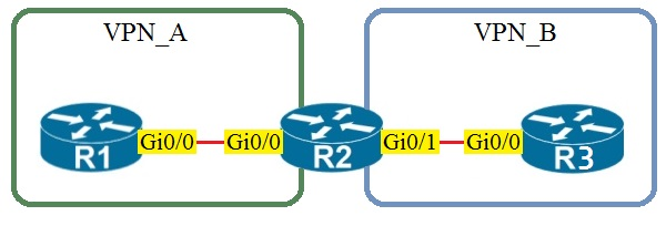
Assuming that R1 is a CE router, which VRF is assigned to Gi0/0 on R1?
Correct. Because R1 is a CE router in a standard MPLS L3VPN topology, it normally does not host the provider VRFs used inside the service provider network. Its Gi0/0 interface toward R2 participates in the global routing table on the CE, which corresponds to the default VRF. The PE router R2 places its customer-facing interface into VPN_A, but that VRF assignment does not automatically extend onto the CE. Unless VRF-Lite is explicitly configured on the CE, the CE interface remains in the default VRF.
Incorrect. VRF VPN_A would be assigned on the PE router interface that connects to the CE for that VPN (R2’s interface toward R1). R1 being a CE implies it is not maintaining separate VRF routing tables for the provider VPN; it simply peers in the default/global table unless VRF-Lite is explicitly used.
Incorrect. VRF VPN_B would be used on the PE interface toward the CE that belongs to VPN_B (R2’s interface toward R3). There is no reason for R1’s Gi0/0 to be in VPN_B, and in standard L3VPN designs the CE does not place interfaces into provider VRFs at all.
Incorrect. The management VRF (often used for out-of-band management, e.g., "vrf Mgmt-vrf" on some platforms) is not used for customer data-plane connectivity. CE-to-PE links for customer routing belong to the global table on the CE and to a customer VRF on the PE, not to the management VRF.
Question Analysis
Core concept: In an MPLS Layer 3 VPN, the provider edge (PE) router maintains customer VRFs, while the customer edge (CE) router typically does not unless VRF-Lite is explicitly configured. Why correct: Because R1 is stated to be a CE router, its Gi0/0 interface toward the PE uses the global routing table by default, which corresponds to the default VRF. Key features: The PE-facing interface on R2 is placed into VPN_A, but that VRF membership is local to the PE and does not automatically apply to the CE side. Common misconceptions: Many candidates incorrectly assume the CE interface must be in the same named VRF as the PE interface, but in standard MPLS L3VPN the CE usually remains in the global table. Exam tips: When a question explicitly says a device is a CE in a standard MPLS L3VPN topology, choose the default/global routing table unless the prompt mentions VRF-Lite or customer-side VRF configuration.
On which protocol or technology is the fabric data plane based in Cisco SD-Access fabric?
VXLAN is the SD-Access fabric data-plane technology. It encapsulates user traffic at the Fabric Edge and transports it across the IP underlay to other fabric nodes. VXLAN provides scalable segmentation using VNIDs and, in SD-Access, can carry policy metadata (SGT) via Group-Based Policy (GBP) extensions. This makes VXLAN the correct answer for the fabric data plane.
LISP is used in Cisco SD-Access primarily as the control-plane protocol. It provides endpoint-to-location mapping (EID-to-RLOC), allowing fabric nodes to discover where a host resides so they can send traffic to the correct fabric node. LISP does not encapsulate and forward the user data traffic across the fabric; that role belongs to VXLAN.
Cisco TrustSec is the policy-plane component in SD-Access. It uses Security Group Tags (SGTs) to enable scalable group-based segmentation and policy enforcement. While SGT information can be carried in the VXLAN encapsulation (via GBP), TrustSec itself is not the fabric data-plane encapsulation/transport mechanism, so it is not the correct answer.
IS-IS is commonly used as an underlay IGP in SD-Access to provide IP reachability between fabric nodes. The underlay ensures that fabric devices can route packets between loopbacks and transit links, which the overlay depends on. However, IS-IS is not the SD-Access fabric data plane; it is an underlay routing protocol, making it incorrect here.
Question Analysis
Core Concept: Cisco SD-Access uses a fabric architecture with distinct control-plane, data-plane, and policy-plane components. The question tests which protocol/technology provides the fabric data plane (how user traffic is encapsulated and forwarded across the fabric). Why the Answer is Correct: The SD-Access fabric data plane is based on VXLAN (Virtual Extensible LAN). In SD-Access, endpoints connect to Fabric Edge nodes, and their traffic is encapsulated in VXLAN to traverse the fabric underlay between Fabric Edge, Fabric Border, and Fabric Intermediate nodes. VXLAN provides Layer 2/Layer 3 overlay connectivity over an IP underlay using a 24-bit VNID, enabling scalable segmentation and multi-tenant designs. In SD-Access specifically, VXLAN is used with Group-Based Policy (GBP) extensions to carry policy information (SGT) in the encapsulation. Key Features / How It Fits Together: 1) Underlay vs Overlay: The underlay is a routed IP network (often using IS-IS, OSPF, or EIGRP) that provides reachability between fabric nodes. The overlay is VXLAN, which carries the actual user traffic. 2) Control-plane mapping: LISP is used as the control-plane to map endpoint identities (EIDs) to fabric node locations (RLOCs). This mapping tells fabric nodes where to send VXLAN-encapsulated traffic. 3) Policy-plane: Cisco TrustSec (SGT) provides group-based segmentation; in SD-Access, SGT information is carried in the VXLAN header using GBP, enabling scalable policy enforcement. Common Misconceptions: - Many confuse LISP with the data plane because it is central to SD-Access, but LISP is for endpoint-to-location mapping (control plane), not packet encapsulation. - IS-IS is commonly deployed in SD-Access, but it is an underlay IGP, not the overlay data-plane technology. - TrustSec is critical for segmentation, but it is a policy mechanism; it does not replace VXLAN encapsulation. Exam Tips: Memorize the SD-Access “three planes” mapping: - Data plane = VXLAN (overlay encapsulation) - Control plane = LISP (EID-to-RLOC mapping) - Policy plane = TrustSec/SGT (group-based policy, carried via VXLAN GBP) Also remember: IS-IS/OSPF/EIGRP are underlay routing choices, not the fabric overlay data plane.

Start Practicing Now
Download Cloud Pass and start practicing all Cisco 350-401: Implementing and Operating Cisco Enterprise Network Core Technologies (ENCOR) exam questions.
Want to practice all questions on the go?
Get the app
Download Cloud Pass — includes practice tests, progress tracking & more.